Makey bitMobile Racer
Assembly Instructions

30-60 min

Ages 8+

What Will You Make?

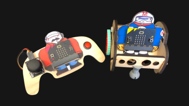
It’s time to get moving! Build a micro-bit to micro-bit powered, Makey:bit fueled racer!

What Will You Learn?

We will be going through the process of unboxing your Makey bitMobile kit parts, to building the controller and assembling the vehicle. Let’s gooooo!

Get out your Makey bitMobile kits and let's get moving!

Bit-Mobile-Kits

Makey bitMobile Racer

Step 1

Put the left side motor into the car with the round part (and cable) facing down and connect the cross brace with a nylon screw.

MakeybitMobile-Racer-Step 1

Step 2

Put the left side motor into the car with the round part (and cable) facing down and connect the cross brace with a nylon screw.

MakeybitMobile-Racer-Step 2

Step 3

Insert the right motor into the car body and then align the pieces so that the right side car body can be connected.
MakeybitMobile-Racer-Step 3

Step 4

It is helpful to mark one side of the motor cables so that you remember which one is which. I like to put a sharpie mark on the left side motor cable close to the black connector piece.
MakeybitMobile-Racer-Step 4

Step 5

Now thread the two cables in the hole under the seat, starting from the front and pulling through the back.
MakeybitMobile-Racer-Step 5

Step 6

Now you can screw on the wheels (use the pointy screws from the Servo bag) and connect the front wheel to the front grill
MakeybitMobile-Racer-Step 6

Step 7

Put the Makey:bit in the bracket of the seat and connect the motors. The left motor is below the right motor and both are on the three pints on the left back of the board. Make sure the orange cable is on the left (and metal of the connector is facing up).
MakeybitMobile-Racer-Step 7

Resources

What Is Happening Here?

The Makey:mobile kit comes with two micro:bits and two Makey:bit boards.  One Makey:bit/micro:bit is preloaded with code for the remote control “pit crew” and the other is preloaded with the “driver” code which controls the Makey:mobile buggy.  

 
The micro:bit has an onboard radio built-in with up to 256 different channels to communicate with other micro:bit boards.  The “pit crew” Makey communicates with the “driver” Makey using this radio.  
 
The Makey:mobile kit is programmed using Microsoft Makecode 
 
The code for the “pit crew” Makey  is here: https://makecode.microbit.org/_iFKPyPfvD1ET
 
The code for the “driver” Makey is here:  https://makecode.microbit.org/_by10fkL77V8u

What Is Next?

Visit the Makey:bit Homepage for fun costume skins, latest product information, projects and resources!


Makey:bit Scratch Gamer

30-60 min

Ages 8+

What Will You Make?

It’s time to play! Use Makey:bit as a controller for your games, to connect the real world with the digital world.

Pressing the buttons will turn on Makey’s LEDs, and you will use these to catch all the tools you can, to earn points, and increase the difficulty.

What Will You Learn?

We will use Scratch block programming to create a fun game, using variables, sounds, sensors, and operations. We will program our Makey:Bit, to interact with the NeoPixels in Makey’s eyes.

Grab your materials...let's get coding!

makey-scratch-materials

Our code is divided into 2 parts:

1) The neopixels with Makey:Bit

2) The game with Scratch

Neopixels + Makey:Bit

Step 1

We are going to open Make Code, here we can program with JavaScript, Python, and of course with a visual block language, the latter is the one we will use.

makey-scratch-step1

Step 2

We are going to go to the Makey-Bit-Projects project repository and download it, clicking on the green “code” button, we select the Zip format. When it finishes downloading, we open the “Makey-bit-scratch-gamer” folder where we have the complete code but divided into parts.

Step 3

We enter the Make Code platform, click on “import” and drag the file “microbit-Create-Makeybit-RGB.hex”, we are ready to start.

If you are new to the platform, the part on the left is our simulator, the middle part is the blocks menu, and the part on the right is our work table. In the upper part, we can change the programming language and the project configuration and in the lower part we have the section to download and save our program

Tip: The project is now ready to work with neopixels, but if you want to use it in another project you need to download its extension, go to Tool –> Extensions –> NeoPixel.

Step 4

We have two blocks of blue color, let’s start with “on start”, we are going to place inside our block “set strip” to NeoPixel on pin 16 with 2 leds as RGB (GRB format)” with this block, we specify that we have two NeoPixels on pin 16. Next, we drag the “strip clear” block, Then we put the “strip show” block

makey-scratch-step4

Step 5

We go to the blue “forever” block, we drag inside the first if “if button A+ B is pressed or button a is pressed or button b is pressed then”, inside the condition we place our second if “if button A+ B is pressed then” and in the first else we place the “if button A is pressed then” and in the last else we place the “strip clear” block.

What it’s doing is checking if we’re clicking any buttons, then checking which button we’re pressing to put the color on the neopixels and if not we turn off the leds.

Step 6

To bring the code to our Makey:bit we click on the three dots next to the “download” button, select “connect device”, follow the steps and download it.

It’s time to test our code, pressing the microbit buttons and we see the neopixels change color.

Great we are already halfway through the project, now we will work on the scratch game Scratch

Scratch + Makey:Bit

Step 7

We go to the Makey:bit Scratch Creator project, we click on “View inside” to start editing it.

On the left, we have our block menu, in the middle our artboard and on the right, we can test our project.

makey-scratch-step7

Step 8

On the right side, we select the “Button2” now in the work area we are going to place our purple block “change background to transparent” and the purple block “hide” under the block “when clicking on this object”

After the block “when the background changes to instructions”, we put next the purple “hide” block. We continue with the block “when the background changes to home” we put the purple block “show” next.

Step 9

Perfect now we select the “1-1” tool, we see the 3 yellow blocks of our main logic and the other blocks that we will need.

Below the yellow “when background changes to home” block, we are going to place the purple “hide” block. Then the “when the background changes to instructions” block, and we put the purple “hide” block.

makey-scratch-step9

Step 10

Now the last yellow block “when the background changes to transparent”, we put next the purple blocks of “show” and “change costume to 1”.

Next we put our blue “set Y to 210” block.

makey-scratch-step10

Step 11

Take the orange “forever” block that has a condition that only one tool per color appears on the screen. We place inside the condition the blue “turn -.1 degrees” block which also has a y-change block, which changes the speed taking into account the current points.

We place after the block “change y in – if touching the color-” and then we put our block “if position in Y < -170 then”.

What we are doing is that when it touches the corresponding color of Makey’s eyes, it changes our costume and gives us a point, but if on the contrary, it touches the ground, it takes away points and disappears.

Step 12

We are going to add a sound when you touch the tools and earn points, we go to the sounds section, here we can import one or create it, remember to check the sound block in the code to specify the name of the sound and it works perfectly.

Step 13

Let’s go to the last step and a very important one, adjust the colors that Scratch detects to earn points. We click on the green flag to start the game, we click on the hand with Makey:bit, the camera is activated. Now turn on Makey’s leds and place him in front of the camera, let’s start with the yellow color in the neo pixels, then in the work section and click on “touching color” we section the pointer, and select the color of the NeoPixels outline , also to have a better result the environment has to have little light.

Tip: To activate the camera, you must accept scratch permissions, we just click on the padlock on the left of the URL.

Step 14

Perfect it’s time to play and have fun, show it to your friends and have fun with Makey:bit!

Finished Project

makey-scratch-final

Resources

What Is Happening Here?

Coding

We are using a visual programming language to create a video game with Scratch, and programming Makey:bit with Make Code.

What Is Next?

It’s time to be creative in programming use different block objects or game dynamics. Then you can use the sensors that this board has like the microphone, accelerometer, and among others, to combine Makey:Bit with Scratch.

You can also find more information:

How to use Microbit with Scratch?: https://scratch.mit.edu/microbit

What is MakeCode and how to use it?: https://www.microsoft.com/es-es/makecode

Servo-Main-Project-Image
I like to Move it Move it: Adding Motors to Makey:bit by Diego
Animatronic Face
Makey:bit Animatronic Face by Kathy Ceceri

About MoonMakers

MoonMakers — led by Camila and Diego Luna —  are a community of creators passionate about knowledge. A Makerspace, an open space with different digital manufacturing machines. And a YouTube channel where we promote science, technology and the maker movement.

MoonMakers have collaborated with companies such as: Sesame Street, Make Community and in Mexico with Educational Television and Fundación Televisa, creating educational content.

We have given workshops throughout the Mexican Republic with: Talent Land, Secretary of Education in Jalisco, Conacyt, Centro Cultural España.

MoonMakers

Makey:bit Jugador de scratch

30-60 min

Ages 8+

¿Qué vas a hacer?

¡Es momento de jugar! Usa a Makey:bit como un control para tus juegos, para conectar el mundo real con el mundo digital.

Al presionar los botones se encenderán los leds de makey, y usarás estos para atrapar todas las herramientas que puedas, para ganar puntos y aumentar la dificultad.

¿Qué aprenderás?

Usaremos programación de bloques en scratch para crear un juego divertido, usando variables, sonidos, sensores y operaciones. Al igual que la programación de nuestra Makey:bit, para interactuar con los neopixels que tiene en los ojos de Makey.

Coge tus materiales... ¡vamos a codificar!

makey-scratch-materials

Nuestro código se divide en 2 partes:

1) los neopixeles con Makey:Bit

2) el juego con Scratch

Neopixels + Makey:Bit

Paso 1

Vamos a abrir Make Code, aquí podemos programar con JavaScript, Python y por supuesto con un lenguaje visual de bloques, este último es el que usaremos.

makey-scratch-step1

Paso 2

Vamos a ir al repositorio del proyecto Makey-Bit-Projects y lo descargamos, haciendo click en el botón verde “code”, seleccionamos el formato de Zip. Cuando termine de descargar vamos abrimos la carpeta “Makey-bit-scratch-gamer” donde tenemos el código completo pero dividido en partes.

Paso 3

Entramos en la plataforma de Make Code, hacemos clic en “importar” y arrastramos el archivo “microbit-Create-Makeybit-RGB.hex”, ya estamos listos para comenzar.

Si eres nuevo en la plataforma, la parte de la izquierda tenemos nuestro simulador, la de enmedio el menú de bloques, la de la derecha es nuestra mesa de trabajo. En la parte superior podemos cambiar el lenguaje de programación y la configuración del proyecto y en la parte inferior tenemos la sección para descarga y guardar nuestro programa

Tip: El proyecto ya está listo para trabajar con los neopixels, pero si quieres ocuparlo en otro proyecto necesitas descargar su extensión, vas a Herramienta -> Extensions -> neopixel.

Paso 4

Tenemos dos bloques de color azul, epezemos con “on start”, vamos a colocar dentro nuestro bloque de “set strip to NeoPixel en el pin 16 with 2 leds as RGB (GRB format)” con este bloque especificamos que tenemos dos neopixels en el pin 16. A continuación arrastramos el bloque “strip clear”, Después ponemos el bloque ”strip show”

makey-scratch-step4

Paso 5

Vamos al bloque azul “forever”, arrastramos dentro el primer if “if button a+ b is pressed or button a is pressed or button b is pressed then”, dentro de la condición colocamos nuestro segundo if “if button a+ b is pressed then” y en el primer else colocamos el “if button A is pressed then” y en el último else colocamos el bloque “strip clear”.

Lo que está haciendo es comprobar si estamos haciendo click en algún botón, luego comprueba qué botón estamos apretando para poner el color en los neopixels y si no apagamos los leds.

Paso 6

Para llevar el código a nuestra Makey:bit hacemos clic en los tres puntos al lado del botón “download”, seleccionamos “connect device”, seguimos los pasos y lo descargamos.

Es momento de probar nuestro código, apretando los botones de la microbit y vemos los neopixeles cambiar de color.

Genial ya estamos a la mitad del proyecto, ahora trabajaremos en el juego en scratch Scratch

Scratch + Makey:Bit

Paso 7

Vamos al proyecto Makey:bit Scratch Creator, hacemos click en “Ver dentro” para comenzar a editarlo.

En la parte de la izquierda tenemos nuestro menú de bloques, en la de enmedio nuestra mesa de trabajo y en la derecha podemos probar nuestro proyecto.

makey-scratch-step7

Paso 8

En la parte derecha, seleccionamos el “Boton2” ahora en la zona de trabajo vamos a colocar  nuestro bloque morado “cambiar fondo a Transparente” y el bloque morado “esconder” debajo de el bloque “Al hacer clic en este objeto”

Después del bloque “Cuando el fondo cambie a Instrucciones”, ponemos a continuación el bloque morado de “esconder”. Seguimos con el bloque de “Cuando el fondo cambie a Inicio” ponemos a continuación el bloque bloque morado de “mostrar”.

Paso 9

Perfecto ahora seleccionamos la herramienta “1-1”, vemos los 3 bloques amarrilos de nuestra lógica principal y los demás bloques que necesitaremos.

Debajo del bloque amarillo “Cuando el fondo cambie a Inicio”, vamos a colocar a el bloque morado de “esconder”. Luego el bloque “Cuando el fondo cambie a Instrucciones”, y colocamos el bloque morado de “esconder”.

makey-scratch-step9

Paso 10

Ahora el ultimo bloque amarillo “Cuando el fondo cambie a Transparente”, ponemos a continuacion los bloques morados de “mostrar” y “cambiar disfraz a 1”.

A continuación ponemos nuestro bloque azul “fijar y a 210”.

makey-scratch-step10

Paso 11

Ahora toma el bloque naranja “por siempre” que tiene una condición para que solo una herramienta por color aparezca en pantalla. Colocamos dentro de la condición el bloque azul “girar -.1 grados” que también  tiene un bloque de cambiar en y, que cambia la velocidad teniendo en cuenta los puntos actuales. Colocamos después del bloque “cambiar y en – sí tocando el color- ” y después ponemos nuestro bloque “si posición en y < -170 entonces”.

Lo que estamos haciendo es que cuando toque el color de los ojos de Makey correspondiente, nos cambia de disfraz y nos aumenta un punto, pero si al contrario toca el suelo nos quita puntos y desaparece.

Paso 12

Vamos a agregar un sonido cuando toques las herramientas y ganes puntos, vamos a la sección de sonidos, aquí podemos importar uno o crearlo, recuerda revisar el bloque de sonido en el código para especificar el nombre del sonido y  funcione a la perfección.

Paso 13

Vamos por el último paso y uno muy importante, ajustar los colores que detecta Scratch para ganar puntos. Hacemos clic en la bandera verde para iniciar el juego, hacemos clic en la mano con Makey:Bit, se activa la cámara. Ahora enciende los leds de Makey y colocalo frente a la camara, empezemos con el color amarillo en los neo pixeles, depsues en la sección de trabajo y hacemos clic en “tocando color” seccionamos el puntero, y selescionas el color del contorno de los neopixels, tambien para tener un mejor resultado el ambiente tiene que tener poca luz.

Tip:  Para activar la cámara, debes aceptar los permisos de scratch, solo hacemos clic en el candado a la izquierda de la URL.

Paso 14

Perfecto es hora de jugar y divertirse, muestraselo a tus amigos y diviértete junto a Makey:bit

Proyecto terminado

makey-scratch-final

Recursos

¿Qué está pasando aquí?

Codificación

Estamos usando un lenguaje de programación visual para crear un videojuego con Scratch, y programar a Makey:bit con Make Code.

¿Qué es lo siguiente?

Es momento de ser creativo en la programación usando diferentes bloque objetos o dinámicas de juego. Luego puedes usar los sensores que tiene esta placa como el micrófono, acelerómetro, y entre otros, para combinar a Makey:Bit con Scratch.


También puedes encontrar más información:

¿Como usar Microbit con Scratch?: https://scratch.mit.edu/microbit

¿Que es MakeCode y como usarlo?: https://www.microsoft.com/es-es/makecode

Servo-Main-Project-Image
I like to Move it Move it: Adding Motors to Makey:bit by Diego
Animatronic Face
Makey:bit Animatronic Face by Kathy Ceceri

Acerca de MoonMakers

MoonMakers — lideradas por Camila and Diego Luna — somos una comunidad de creadores apasionados por el conocimiento. Un Makerspace, un espacio abierto con diferentes máquinas de fabricación digital. Y un canal de YouTube donde promovemos la ciencia, la tecnología y el movimiento maker.

MoonMakers ha colaborado con empresas como: Sesame Street, Make Community y en México con Televisión Educativa y Fundación Televisa, creando contenido educativo.

Hemos imparto talleres por la República Mexicana con: Talent Land, Secretaría de educación en Jalisco, Conacyt, Centro Cultural España.

MoonMakers

I Like to Move it Move it: Adding Motors to the Makey:bit

30-60 min

Ages 11+

What Will You Make?

Learn how to control servo motors with the micro:bit then build a small buggy for the Makey:bit.

What Will You Learn?

Learn how to install and control Servo motors with the Makey:bit.

Learn how to install Extensions in MakeCode.

Learn how to use Function blocks in MakeCode.

Connect the Servo Motors

Step 1

Look on the back of the Makey:bit at the array of pins behind the head. On the left side of the array, there are two rows of 3 pins dedicated to servo motors. The top row is labeled (left to right) P2 Servo, BAT and GND. The second row is labeled P0 Servo, BAT, GND.

Step 2

Insert your servo motors into each row with the orange wire to the left (into P0 or P2).

Add the Servo Motor extension

Step 1

Servo motors can be controlled using the Pins blocks but it is easier to control them if you add the Servo Extension. In your MakeCode program, click on Extensions.

Step 2

Select the Servo extension (if it is not visible on the first page, search for Servo).

Test Out Some Code

Step 1

Before you build something, try out some simple code to familiarize yourself with how to control the motor. From the “Input” tab, select “on button A pressed.”

Step 2

Now select from the servos tab and pick a “continuos servos” block. Put two of these blocks into the Input tab and select one from P0 and the other from P2.

Step 3

Select a “pause” block from the “Basic” tab.

Step 4

Select a “Stop servo” block from the “Servos” tab and use two of them to stop the servo.

Step 5

Upload the program and test it out

Build Something!

Step 1

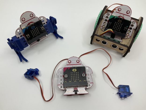
Robots come in many shapes and sizes. Build your own or pick one of the projects designed specifically for the Makey:bit: Walking Robot or Robot Buggy.
Follow the assembly instructions for the project you pick. 

Step 2

Once assembled, take a close look at the position of the motors in your robot. Notice that they are mirroring each other. Almost any robot design will have the two motors positioned as mirror images of each other. What does that mean for your code? You probably guessed it… forward for one motor means reverse for the other motor! Update your code and test it out.

Build Something!

Step 1

Now that we know how to control motors and LEDs on the micro:bit and the eyes, we can use Functions to streamline our code for commonly used commands. In this case, let’s create a command for the robot that we will call “goForward”. Start by clicking on the “Advanced” tab.

Step 2

Now select the “Functions” tab and click on “Make a Function.”

Call the function “goForward.”

Note: It is common naming convention for Functions to start with a lower case letter. This isn’t a requirement in MakeCode but we will use this convention.

Step 3

Now we can combine code within the Function block “goForward.” Let’s add a face that represents going forward. We can also make the colors of the eyes green to represent “goForward” and, of course, let’s make the motors turn in such a way that the robot goes forward.

Test and upload the code.

Step 4

Now try making a “goRight” and a “goLeft” block or even a “goBackwards” block.

What Is Happening Here?

What is a Servo Motor?

According to Wikipedia “A servomotor is a closed-loop servomechanism that uses position feedback to control its motion and final position. The input to its control is a signal (either analogue or digital) representing the position commanded for the output shaft.”

What does this mean? Essentially, a servo motor is a precise motor that is often used in robotics. There are two types of servo motors: continuous and 180. A continuous motor can spin forward and backward continuously and is most commonly used for wheels of a robot. A 180 motor can only move 180 degrees and is used when we want to have very precise control.

Servo motors come in many shapes and sizes and the most commonly used size for beginner maker projects are “micro-servo motors.” If the servo is marked “FS90R” it is a continuous servo. If you are unsure what kind of servo you have, look up online the part number marked on the servo to confirm before proceeding

About the Makey:bit

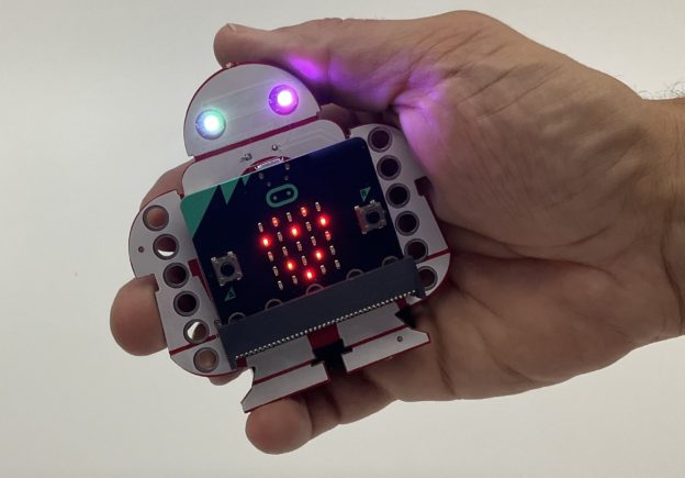
The Makey:bit Adventure Board is the perfect way to get started with microcontrollers. With this exclusive Maker Shed kit, you’ll be able to easily launch into the world of electronics and create amazing projects.

This all-in-one board includes everything you need to get started, including a built-in LED, buzzer, and various sensors. Plus, the Makey:bit is compatible with all kinds of additional modules, so you can easily expand your creativity.

So what are you waiting for? Get the Makey:bit Adventure Board today and start supercharging your microcontrollers!

Are you looking for a way to supercharge your microcontrollers? If so, then you need the Makey:bit Adventure Board! This exclusive Maker Shed product is packed with features that will take your microcontrollers to the next level. With the Makey:bit, you’ll be able to launch into the realm of microcontrollers and unleash their full potential. The Makey:bit is loaded with features that make it an essential tool for anyone looking to get the most out of their microcontrollers.

Start Here: Bring Makey Alive with a Beating Heart

less than 30 min

Ages 11-13

What Will You Make?

Make a simple “beating heart” animation using the grid of LED lights on the front of the micro:bit board.

What Will You Learn?

The Flashing Heart shows you how to write and upload your first program to the micro:bit using free, online Microsoft MakeCode software. It’s based on the tutorial on the micro:bit web site at https://makecode.microbit.org/ This version adds a few steps, so you can move along in your coding adventure quicker!

Prepare the Makey:bit

Step 1

Insert the batteries into the back of the Makey:bit. Make sure the batteries are facing the right in the correct direction.

Step 2

Now insert the micro:bit in the front holder, with the buttons facing out.

Step 3

Turn on the Makey:bit with the red on/off switch in the back.

Step 4

Extra! If this is a brand-new micro:bit, it should have a fun little pre-loaded program that which provides a guided tour of the micro:bit. Turn on the Makey:bit with the red on/off switch in the back and take a few minutes to follow the directions and play around with the board.

Write Your Code

Step 1

The micro:bit can be programmed in multiple programming languages including micro Python and the Arduino IDE, but the easiest way to program it is with Microsoft MakeCode. Go to https://makecode.microbit.org/ to get started.

Step 2

Open a new project on the micro:bit MakeCode website (https://makecode.microbit.org/). You’ll see a column of different categories of blocks.

Step 3

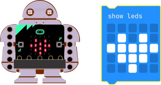
Click on Basic. When the menu of blocks in the Basic category opens, click on the “show LEDs” block and drag it into the workspace. This block lets you turn the micro:bit’s LEDs on and off. Click on the little boxes to draw a heart with lights.

Step 4

When you’re done, drag the “show leds” block inside the “forever” block that’s already in the workspace.

Upload the Program

Step 1

Insert the USB cable into the micro:bit, click the Download button, and follow the instructions to download the program to the board. The lights you selected on your board should light up.

Make the Heart Beat

Explaination

What if we want to make the heart look like it’ is beating? We can do that the same way cartoon animators make things look like they’re moving: by replacing the image with a slightly different one. If you switch them quickly enough, your brain thinks it’s watching an object moving or changing shape! In this case, we’ll go back and forth between two versions of the heart image.

Step 1

First, add another “show LEDs” block underneath the first. On the micro:bit simulation on the screen, you’ll see the heart drawing flash on and off.

Next, let’s draw a slightly different heart in the second “show LEDs” block.

Step 2

Use the “pause” block between the multiple “show LEDs” blocks to slow down the transition and animate the image.

Step 3

Let’s make it look like it is pulsing over and over. We do this by putting it inside a “forever” loop.

When the micro:bit simulation on the screen reloads, the image will start to pulse!

Step 4

Finally, don’t forget to download the program to see how it works on the actual micro:bit board.

What Is Next?

Explore Animation

Now that you have figured out how to animate a flashing heart, what else can you add to the makey:bit?

Can you design an animated animal or face? Here are some ideas https://microbit.org/projects/make-it-code-it/animated-animals/. Make your own and animate it.

Explore other blocks that control the LED screen. What does the “show string” block do? The “show arrow” block uses an onboard sensor. Which sensor do you think it is using?

Build some code using two different blocks not covered in this tutorial.

About the Makey:bit

The Makey:bit Adventure Board is the perfect way to get started with microcontrollers. With this exclusive Maker Shed kit, you’ll be able to easily launch into the world of electronics and create amazing projects.

This all-in-one board includes everything you need to get started, including a built-in LED, buzzer, and various sensors. Plus, the Makey:bit is compatible with all kinds of additional modules, so you can easily expand your creativity.

So what are you waiting for? Get the Makey:bit Adventure Board today and start supercharging your microcontrollers!

Are you looking for a way to supercharge your microcontrollers? If so, then you need the Makey:bit Adventure Board! This exclusive Maker Shed product is packed with features that will take your microcontrollers to the next level. With the Makey:bit, you’ll be able to launch into the realm of microcontrollers and unleash their full potential. The Makey:bit is loaded with features that make it an essential tool for anyone looking to get the most out of their microcontrollers.

Makey:bit Brand New Eyes!!

less than 30 min

ages 11-13

What Will You Make?

This project shows how to control the color of the Makey:bit’s eyes and write a program to randomly change the eye color every time you shake the Makey:bit + micro:bit.

What Will You Learn?

Learn how to control the Makey:bit eyes by learning about programmable, addressable LEDs controlled by the NeoPixel driver.

Learn how to install Extensions in MakeCode.

Learn how to use math blocks in MakeCode.

What are the Makey:bit eyes?

Neopixels

The eyes of the Makey:bit are NeoPixel-compatible Light Emitting Diodes (LED) that can be individually programmed. Each eye has a Red, Green and Blue (RGB) LED and the brightness and intensity of each color can be controlled through code. Multiple Neopixels can also be put together on a strip or grid and can be individually controlled based on the order they are on the strip (starting with 0 through however many NeoPixels we have).

Adding NeoPixel Extension

Step 1

Neopixels are not standard with every micro:bit so first step is to add the blocks needed to control them in MakeCode. In programming, blocks of code that are used for a specialized purpose are often called “drivers” or “libraries.” In MakeCode, we can add new drivers and libraries by going to a section called “Extensions.”

Step 2

Open your beating heart program in MakeCode. Click on the “Advanced” tab in the code blocks section.

Step 3

Scroll to the bottom of the blocks and click on “Extensions”

Step 4

On the top row there is a square for the Neopixel drivers, click on it.

Program the Eyes

Step 1

Now you should be back in the MakeCode programming environment and a new tab should be visible called “Neopixel”.

Step 2

First you have to tell the micro:bit that NeoPixels are connected to it. Click on the Neopixel tab and drag the “set strip…” block to the “on start” block. On the Makey:bit, the NeoPixels are connected to pin 16 so select P16 and since there are two eyes, select “2” LEDs.

Step 3

NeoPixels are very bright when on full (default) so it is recommended to use the “set brightness” block to set the brightness to roughly half (they can go from 0-255 so 100 is a good starting point).

Step 4

Now that the micro:bit knows that there are NeoPixels connected. Let’s turn on the colors. Use the “strip set pixel color…” block and put it inside the forever loop.

Remember, the NeoPixels start at 0 so even though there are two Neopixels, the first one (left) is “0” and the second one (right) is “1”.

Don’t forget to use the “show” block otherwise nothing will happen.

Step 5

Upload the program.

Random Color Generator

Step 1

Neopixels make colors by combining red, green and blue.

On the “more” menu of the Neopixels tab, there’s a block that lets us make our own colors by combining them ourselves.

In this block, 0 is “off” and 255 is maximum brightness. When all are at 255, the color looks white. When only one color is on, the color is that color… etc.

You can drag this block where the color name is currently showing and make your own colors by changing the values directly.

Step 2

If you want to explore how many colors the NeoPixels can make, you could do it manually but that would take a long time. Instead, let’s explore an alternative approach.

Step 3

Now is a good time to explore the “Math” blocks. Click on that tab and select the the “Random” block.

If you put in a random number between 0-255 into the value, now, every time the heart beats, a new random number and color will appear.

Upload the code and observe how the Makey:bit functions.

Sample Code

Link to MakeCode: https://makecode.microbit.org/_6k7dUThyPLo2

Note: In the sample code there’s an additional math step where we pick a random number between 1-25 and then multiply the number by 10… Can you guess why that was done?

What Is Happening Here?

Intro to Makey:bit

This is an introductory programming project for the Makey:bit that explains how to add extensions and program features of the Makey:bit.

This is also an introductory project to explore how colors are most commonly generated in most computer screens, through a combination of “RGB” (Red, Green and Blue) Lights. The Makey:bit eyes are RGB LEDs and the final code will generate thousands of different colors by changing the level of Red, Green or Blue in the eyes.

About the Makey:bit

The Makey:bit Adventure Board is the perfect way to get started with microcontrollers. With this exclusive Maker Shed kit, you’ll be able to easily launch into the world of electronics and create amazing projects.

This all-in-one board includes everything you need to get started, including a built-in LED, buzzer, and various sensors. Plus, the Makey:bit is compatible with all kinds of additional modules, so you can easily expand your creativity.

So what are you waiting for? Get the Makey:bit Adventure Board today and start supercharging your microcontrollers!

Are you looking for a way to supercharge your microcontrollers? If so, then you need the Makey:bit Adventure Board! This exclusive Maker Shed product is packed with features that will take your microcontrollers to the next level. With the Makey:bit, you’ll be able to launch into the realm of microcontrollers and unleash their full potential. The Makey:bit is loaded with features that make it an essential tool for anyone looking to get the most out of their microcontrollers.

Makey:bit Animatronic Face

About 3 hours

Ages 8+

What Will You Make?

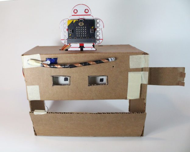
Makey:bit controls this animatronic face. It can open and close its mouth, roll its eyes, and raise and lower its unibrow.

What Will You Learn?

You’ll learn to control servos with micro:bit and MakeCode.

Prepare Your Materials

Step 1

For the face, make or take a box with two flaps that meet at the middle. Turn it so one flap opens and closes from the bottom – this is the mouth. Tape the upper flap closed. This is where the eyes and unibrow will go.

Step 2

For a push rod, straighten a paperclip, leaving the bends at the ends to use as hooks.

Step 3

For the eyes, find or cut a cardboard tube a little shorter than the width of the box.

Step 4

For the arm (which holds up the eyes tube), cut a strip of cardboard just wide enough to fit inside the tube without rubbing. It should be long enough to fit at least halfway into the tube, with enough hanging outside for the arm.

Attach a Servo to the Box to Open the Mouth and Roll the Eyes

Step 1

Mark a spot for a servo on one side of the box, about an inch away from the front and even with the level of the eyes. Trace around the servo at that spot, and cut out a hole to hold it snugly. Insert the servo into the hole from the inside, so the cable is outside the box.

Step 2

Snap a servo horn onto the servo. Mark one arm (or a spot along the edge if you’re using the circle horn) to be your measuring point. It will point up when the mouth is closed.

Step 3

To calibrate the servo so it points the right way:

  1. Turn the horn to the right as far as it will go.

  2. The measuring spot should point directly to the right (the 3 o’clock position). If it doesn’t, take it off and re-attach it so it does.

  3. Remove the servo horn.

  4. If you are leaving out the eyes tube, hook the smaller end of the paperclip through a hole along the servo horn and go directly to Finish the Face from here.

Step 4

Cut out a circle of cardboard about ¼ inch bigger around than the cardboard tube.

Step 5

Tape the servo horn to the middle of the circle.

Step 6

Tape one end of the tube to the circle. Make sure the servo horn is facing out!

Step 7

Hook the smaller end of the paperclip through the cardboard circle. If you need to save space, you can trim it later to an egg shape, leaving an overhang where the paperclip is attached.

Insert the Arm

Step 1

Snap the eyes tube onto the servo with the measuring point facing up.

Step 2

Hold the tube straight across, and mark where the top and bottom of the tube would meet the box if it were long enough. Cut a slot for the cardboard strip between those marks.

Step 3

Insert the arm strip through the slot from the outside and into the eye tube.

Step 4

Bend the outside of the arm forward to hold it in place. If you need to remove or adjust the eye tube, gently pull the arm strip out of the box.

Finish the Face

Step 1

Make sure the measuring point on the servo horn is pointing up.

Step 2

To attach the loose hook on the paper clip to the mouth, poke a hole through it. You can also tape on an extra piece of corrugated cardboard with the channels running sideways and insert the hook into the channel that fits best. Test to make sure you can pull and push the mouth open and closed.

Step 3

Cut the holes for eyes, making sure they are even with the tube inside the box. Draw eyes on the tube with the mouth open and with it shut. Write “back” on the back of the tube so you can re-connect it correctly if you need to.

Add the Unibrow

Step 1

Use a straw or pipe cleaner (or both) to make a brow that bends in the middle. Attach one end to the face so it can pivot. If you’re using a pipe cleaner, you can poke a hole right in the cardboard and insert the end. With a straw, hold it one with a small screw or pin.

Step 2

The servo motor for the brow goes inside the box. The top of the servo motor sticks out the front of the face, above the eye. (Duh.) Trace and cut out a hole so just the top of the servo sticks out. Use plenty of tape to hold the servo motor in place.

Step 3

Tape the loose end of the brow to a servo horn. Wrap some masking tape around them to hold them together.

Step 4

Snap the horn onto the servo with the brow straight.

Connect the Makey:bit

Step 1

Insert the micro:bit into the Makey:bit.

Step 2

Stand the Makey:bit on top of the Animatronic Face box. Secure it on with some kind of attachment, tape, or glue, such as a strip of peel-and-stick Velcro or Legos.

Step 3

Cut a hole in the top of the box near the Makey:bit big enough for the ends of the servo motor cables to pass through.

Step 4

Pull the cable for the servo attached to the mouth and eyes out through the hole. Plug it into the Makey:bit using the pins marked Servo A (SRVA). This servo will be programmed using pin P0.

Step 5

Pull the cable for the brow through the hole the same way. Plug it into the Makey:bit using the pins marked Servo B (SRVB). This servo will be programmed using pin P2.

Troubleshooting

If your face is not moving correctly, try these tips:

  1. Tuck in loose wires.

  2. Bend the paperclip if needed to make the mouth open and close correctly.

  3. Make sure the paperclip doesn’t hit anything as it moves.

  4. Check that the eye tube has not detached from the servo.

Write the MakeCode Program

Sample Code

Sample Code: https://makecode.microbit.org/_U7fdKWMA2WLX 

This program will make the mouth open and close, the eye tube roll, and the unibrow scowl or look happy. To test out the code, it uses Button A to move the mouth and eyes, and Button B to move the unibrow. When it’s working, check out additional ideas to make your Animatronic Face seem more alive!

Remember, you may need to set your servos in the opposite direction of these instructions, depending on how you placed your servos in your model!

Step 1

On start, set both servos – P0 and P2 – to 90 degrees. This makes sure the mouth is closed and in the neutral position for the motors. (If the mouth is open too much, readjust your paperclip and/or your eyes tube.)

Step 2

To open the mouth and make the eyes roll up, make servo P0 turn to the left:

    1. Type in or use the slider to adjust the “set servo angle” block for P0 to about 10 degrees.

    2. Insert a pause of about one second (1000 milliseconds, or ms).

    3. Use another “set servo angle” block to set it back to 90.

    4. Place the blocks inside a repeat block set for as many times as you want the mouth to open and close.

    5. Place the entire stack inside an “on button A pressed” block so you can trigger the action.

Step 3

To make the unibrow point down, go back to the middle, and then point up, swing the servo at P2 in both directions:

    1. Type in or use the slider to adjust the “set servo angle” block for P2 to about 10 degrees.

    2. Insert a pause of about one second.

    3. Use another “set servo angle” block to set it back to 90. Add another pause.

    4. Use a third “set servo angle” block to move the servo to 170 degrees, the opposite direction. Add another pause.

    5. Use the last “set servo angle” block to set it back to 90.

What Is Next?

More Ideas

  1. Program the lights to flash or show images that match your animatronic face’s moods.

  2. Add Music blocks to make the mouth talk. Scroll down to the bottom of the Music block menu to find the “play sound” block. It includes sounds like “giggle” and “yawn.” Or use notes from the Tone section of the Music menu to create your own “tonal” language!

  3. Add “on sound” blocks from the Input menu to make the mouth “answer” with tones when it hears someone talk to it.

About the Makey:bit

The Makey:bit Adventure Board is the perfect way to get started with microcontrollers. With this exclusive Maker Shed kit, you’ll be able to easily launch into the world of electronics and create amazing projects.

This all-in-one board includes everything you need to get started, including a built-in LED, buzzer, and various sensors. Plus, the Makey:bit is compatible with all kinds of additional modules, so you can easily expand your creativity.

So what are you waiting for? Get the Makey:bit Adventure Board today and start supercharging your microcontrollers!

Are you looking for a way to supercharge your microcontrollers? If so, then you need the Makey:bit Adventure Board! This exclusive Maker Shed product is packed with features that will take your microcontrollers to the next level. With the Makey:bit, you’ll be able to launch into the realm of microcontrollers and unleash their full potential. The Makey:bit is loaded with features that make it an essential tool for anyone looking to get the most out of their microcontrollers.

Makey:bit Cereal Box Plotter

1-3 hours

Ages 8+

What Will You Make?

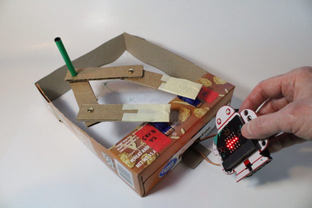
In this project, you will create a programmable drawing robot, also called a plotter. The Makey:bit and the micro:bit control two servos, which make the arms move around. The micro:bit’s accelerometer lets you use the Makey:bit as a tilt controller and tell the plotter to draw back and forth and side to side across the paper!

What Will You Learn?

You’ll learn to use the input from an accelerometer to control servos with MakeCode and a micro:bit.

Prep the Base

Step 1

The base of the plotter is a folded-over ridge of cardboard that holds the servos, and a flat surface that holds the drawing paper. Cereal box cardboard has a coating on the outside that prevents the marker from soaking through. To make it out of a sheet of cardboard, fold the end of a rectangle over twice and tape it as shown.

Step 2

To make the plotter base out of a cereal box, lay the box down on its back. Draw a line across the box about 2 inches up from the bottom. Press hard. Draw another line about 2 inches above the first.

Step 3

Cut one top edge of the box from the opening at the top to the first line. Repeat with the other edge. This will turn the front of the box into a flap you can fold back.

Step 4

Fold the flap up along the second line. Then fold it down along the first line. Press the rest of the flap into the bottom of the box so it lays flat. If you want, trim the other end of the box to fit around the flap. Tape everything in place.

Insert the Servos

Step 1

Place the servos on the stand, trace around them, and cut out the shapes. 

Step 2

Cut a hole in the back of the box. Insert the servos into the hole on top. Pull the servo cables out through the hole in the back.

Step 3

To calibrate the servos so they face front when set at neutral (90 degrees), follow these steps with each one:

  1. Attach a servo horn with an arm facing straight ahead. 
  2. Gently turn the servo horn all the way to the right, as far as it will go. If the arm is not pointing to the right (3 o’clock position), then remove the servo horn and snap it back on in the correct position. 
  3. Turn the servo so the arm points straight ahead again.

Make the Arms

Step 1

Cut four strips of sturdy cardboard, about 1 inch wide by 4 or 5 inches long.

Step 2

Connect the ends of two strips with a brad. Use the sharp pencil to make a starter hole if needed. You now have an arm that bends at the “elbow.” Repeat with the other two strips.

Step 3

Take the end of one arm and overlap it with the end of the other arm. To make a holder for the marker, poke the sharp pencil through both layers of cardboard.

Step 4

Insert the marker through both layers of cardboard. With the cap end of the marker facing down, play around with the ends of the arms. See how you can move them to make the pen go in different directions.

Step 5

Tape the loose ends of the arms securely to the servo horn.

Step 6

Test it with some paper cut down to fit inside the box. See where the marker goes to the right, left, front and back of the box.

Connect the Makey:bit to the Servos

Step 1

Insert the micro:bit into the Makey:bit.

Step 2

Plug the cable wires for one servo over the pins marked SRVA. Write P0 next to the servo.

Step 3

Plug the cable wires for the other servo over the pins marked SRVB. Write P2 next to the servo.

Step 4

Use the data cable to connect the micro:bit to your computer and get ready to code!

Coding Instructions

Sample Code

Sample Plotter Code https://makecode.microbit.org/_XMd1evDoHfMm 

Code the arms to move in the direction you tilt the Makey:bit. 

NOTE: Only move the servo(s) a little way to the right or left. This will help you avoid jerking the plotter arms around too far and damaging the cardboard or the electronics. If needed, increase the movement in small steps until you reach the amount you want.

Coding micro:bit

  1. On start, set the servos to 90 degrees (neutral position).
  2. From Input, grab the “on shake” block.
  3. Open the drop-down menu and choose “tilt left.” 
  4. Add a stack of blocks to make the servos turn left.
  5. Download and test your code. 
  6. When it’s correct, duplicate the stack and  change everything to turn to the right.
  7. Add comments to remember what your code does!

About the Makey:bit

The Makey:bit Adventure Board is the perfect way to get started with microcontrollers. With this exclusive Maker Shed kit, you’ll be able to easily launch into the world of electronics and create amazing projects.

This all-in-one board includes everything you need to get started, including a built-in LED, buzzer, and various sensors. Plus, the Makey:bit is compatible with all kinds of additional modules, so you can easily expand your creativity.

So what are you waiting for? Get the Makey:bit Adventure Board today and start supercharging your microcontrollers!

Are you looking for a way to supercharge your microcontrollers? If so, then you need the Makey:bit Adventure Board! This exclusive Maker Shed product is packed with features that will take your microcontrollers to the next level. With the Makey:bit, you’ll be able to launch into the realm of microcontrollers and unleash their full potential. The Makey:bit is loaded with features that make it an essential tool for anyone looking to get the most out of their microcontrollers.

FEEDBACK